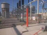
In the operation and maintenance of 35KV substations and high voltage distribution systems, preventive testing is an important means to evaluate equipment insulation status and detect potential defects. Test items cover multiple categories including transformers, switchgear, instrument transformers, surge arresters, power cables, and grounding grids, involving a wide variety of test equipment. How to configure scientifically and avoid omissions or duplicate purchases is a key issue for power engineering and operation and maintenance units during the equipment selection stage.
This article, based on DL/T 596 "Preventive Test Code for Electric Power Equipment" and GB 50150 "Standard for Handover Test of Electrical Equipment Installation Engineering", combined with the actual needs of 35KV voltage level, presents a complete preventive test equipment configuration scheme for reference.
I. Selection Basis and Basic Principles
Preventive test equipment selection should follow these principles:
Standards first. Handover tests follow GB 50150, preventive tests follow DL/T 596. The standards specify the voltage, time, cycle, and acceptance criteria for each test item, which are the fundamental basis for equipment selection.
Comprehensive coverage. The configuration scheme should cover all types of equipment under test in the substation, including main transformers, high voltage switchgear, GIS combined apparatus, instrument transformers, surge arresters, power cables, and grounding grids.
Parameter margin. Key parameters such as voltage, current, and capacity should cover the maximum values of the equipment under test, with a 10%~20% margin reserved to adapt to future equipment upgrades or higher voltage level test requirements.
Consider site conditions. Site factors such as power supply capacity, transportation conditions, working space, and electromagnetic interference intensity directly affect the selection of equipment capacity, volume, and anti-interference capability.
II. Transformer Test Equipment Configuration
Transformers are the core equipment of a substation, with the most test items and the most complex configuration.
Winding DC resistance measurement: Configure a three-phase 10A DC resistance tester, output current 10A, range 1μΩ~2kΩ, accuracy 0.2 class. Simultaneous three-phase measurement can significantly shorten test time, suitable for DC resistance measurement of large and medium-sized transformers.
Transformation ratio and vector group measurement: Configure a transformation ratio and vector group tester, measuring range 1~10000, accuracy 0.2 class. The equipment should have automatic vector group identification, enabling automatic identification for transformers with unclear nameplates or unknown winding connections.
Insulating oil test: Configure a KDJJC-80 insulating oil dielectric strength tester, output voltage 80kV, accuracy 1%, for insulating oil withstand voltage test; configure an oil dielectric loss tester, variable frequency output 0.5~10kV, 45/55Hz, for insulating oil dielectric loss measurement. The variable frequency measurement method can effectively avoid on-site power frequency interference and ensure data stability.
Short-circuit impedance and loss measurement: Configure a transformer no-load and load capacity tester, output 0~100A, 0~750V, used to measure short-circuit impedance, load loss, no-load current, and no-load loss, and to calculate transformer capacity.
Tap changer measurement: Configure a transformer on-load tap changer tester, range 0.1~40Ω, time resolution 1ms~256ms, capable of recording transition waveforms, used to determine whether the tap changer switching process is normal.
Switch mechanical characteristics and circuit resistance: Configure a high voltage switch dynamic characteristics tester (range 0~20m/s, 0~900mm) for circuit breaker and SF6 switch mechanical characteristics testing; configure a 100A circuit resistance tester (range 0~1999.9μΩ) for switch and GIS control equipment circuit resistance measurement.
Vacuum degree measurement: Configure a vacuum switch vacuum degree tester, range 10⁻⁵~10⁻¹Pa, for vacuum circuit breaker interrupter vacuum degree detection.
III. Instrument Transformer and Surge Arrester Test Equipment Configuration
Voltage transformer induced withstand voltage: Configure a 10KVA triple frequency generator for voltage transformer induced withstand voltage test.
Instrument transformer volt-ampere characteristics: Configure an instrument transformer volt-ampere characteristics tester, output 0~1000V, 10A, for VA characteristic testing.
DC withstand voltage and surge arrester test: Configure a 120KV/2mA DC high voltage generator for DC withstand voltage, DC leakage, and surge arrester DC reference voltage tests; configure a zinc oxide surge arrester tester, output 0~100V, current 0~10mA, for surge arrester resistive current and active/reactive component measurement.
IV. Cable and Withstand Voltage Test Equipment Configuration
Cable fault detection: Configure a cable fault tester, range 0~15km, resolution 1m, for precise cable fault point location.
AC withstand voltage test: Configure a 135KVA/108KV XLPE cable AC withstand voltage resonance device. This device adopts the LC series resonance principle and can meet the withstand voltage test of 10KV XLPE cable with a length of 3000 meters, and 35KV XLPE cable with a length of 1000 meters. The resonance voltage boosting method requires relatively low on-site power supply capacity and is suitable for substation site operation conditions.
Power frequency withstand voltage measurement: Configure a 10KVA/100KV power frequency AC high voltage test device, output 0~100KV, capacity 10KVA, as a supplement to conventional high voltage withstand voltage measurement.
V. Grounding Grid and Auxiliary Test Equipment Configuration
Grounding system: Configure a grounding resistance tester (range 0~2000Ω) for grounding grid resistance measurement; configure a 10A grounding down-conductor continuity tester for transformer neutral point grounding system continuity testing.
Relay protection: Configure a microcomputer relay protection tester, output six-phase current and six-phase voltage, for relay protection device debugging and calibration.
Insulation measurement: Configure a smart insulation resistance tester, output 500~1000V, 2500V~5000V, range 1000GΩ, for transformer winding insulation resistance and absorption ratio measurement.
Test voltage measurement: Configure a 100KV AC/DC voltage divider, output AC/DC 0~100KV, for precise measurement of test voltage.
VI. Selection Notes
Parameter matching. Equipment voltage, current, capacity, and other parameters should match the maximum test requirements of the equipment under test, with appropriate margin reserved.
Anti-interference capability. The electromagnetic environment at substation sites is complex. It is recommended to prioritize equipment with variable frequency measurement, digital filtering, and other functions to ensure stable and reliable data.
Site adaptability. Portable equipment should preferably use built-in lithium batteries, be lightweight, and have a protection rating of IP54 or above to reduce dependence on on-site mains power.
Equipment expandability. Prioritize equipment that can cover multiple types of test objects through accessory expansion or combination. For example, a series resonance device can cover withstand voltage test requirements for cables, GIS, transformers, and other equipment through series-parallel combination of reactors.
After-sales and calibration. Confirm whether the supplier can provide regular calibration services, calibration certificates, and after-sales technical support, to avoid affecting test arrangements due to long equipment calibration or repair cycles.
Advantages of complete configuration. Adopting a complete configuration scheme ensures matching interfaces, unified operation training, and clear after-sales responsibility, helping to improve overall test efficiency.
Conclusion
The selection of 35KV high voltage preventive test equipment should be based on test items, guided by standards and regulations, and reasonably configured according to actual site conditions. The above complete scheme covers the test requirements of main equipment including transformers, switches, instrument transformers, surge arresters, cables, and grounding grids, and can be appropriately adjusted according to the actual scale and equipment types of the substation.
For specific equipment technical parameters or customized selection schemes, please contact us.
Wuhan KEDE Zhongwei Electric Co., Ltd.
Tel: 027-86861986
Email: whkdz@163.com