![KDXZ-810kVA/270kV Series Resonance Test System – Field Application at a Hydropower Station Step-Down]()
17 Jul-2026
I. Project Background
In July 2026, Wuhan Kedi Zhongwei received a field test support request from a hydropower station renovation project in Ya‘an, Sichuan. The station was undergoing an upgrade of its step-down substation equipment, and the newly installed 10kV and 35kV cables, as well as 110kV GIS equipment, required AC withstand voltage testing prior to commissioning to verify insulation performance.
The customer had previously purchased our KDXZ-810kVA/270kV Variable Frequency Series Resonance Test System, but their team was not yet familiar with on-site assembly, reactor configuration, or operational procedures, and required on-site technical training and operational guidance.
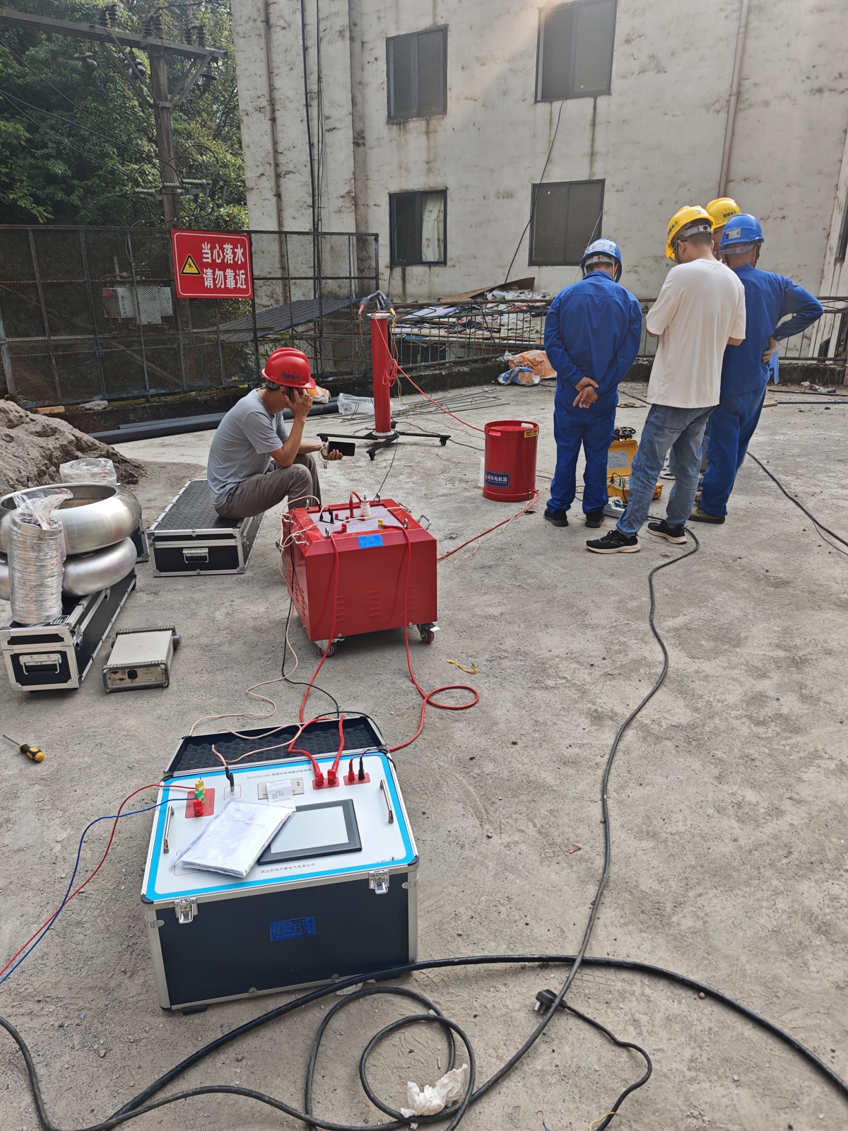
Upon receiving the request, Wuhan Kedi Zhongwei deployed technical engineers with the complete system to the site. The project was located within the hydropower station compound, where workspace was relatively constrained. Equipment placement and wiring had to be carried out under limited spatial conditions, placing higher demands on the system's compact design and flexible combination capabilities. Our engineers worked closely with the customer‘s team to complete the assembly and commissioning efficiently while maintaining all required safety clearances.
II. Equipment Under Test and System Selection Basis
The equipment tested in this project consisted of newly installed power apparatus for the hydropower station‘s step-down substation, with specifications and withstand voltage requirements as follows:
| Equipment Under Test |
Specification |
Test Voltage |
Duration |
Frequency Range |
| 10kV XLPE Cable (station service feeder) |
300mm², approx. 1.5km |
≤22kV |
5min |
30-300Hz |
| 35kV XLPE Cable (step-down substation incoming line) |
300mm², approx. 0.8km |
≤52kV |
60min |
30-300Hz |
| 110kV GIS (main transformer incoming bay) |
— |
≤265kV |
1min |
30-300Hz |
System Selection Calculation Basis:
Taking the 35kV cable as an example: the capacitance of 300mm² XLPE cable is approximately 0.18-0.22μF/km. For 0.8km of cable, the total capacitance is approximately 0.16μF. When the resonance frequency is set to approximately 45Hz, the required inductance is:
L = 1 / (4π²f²C) ≈ 1 / (4 × 9.87 × 2025 × 0.16×10⁻⁶) ≈ 78H
Each reactor in our system has an inductance of 40H. A parallel configuration of 2 reactors provides approximately 20H, which, with appropriate compensation, meets the resonance frequency requirements.
For the 110kV GIS, the capacitance of a single bay typically ranges from 500pF to 1500pF. The GIS for the main transformer incoming bay at this substation was calculated to have a capacitance of approximately 1200pF. At a resonance frequency of 135Hz, the required inductance is approximately 1.2H. All 6 reactors connected in series can achieve the 265kV test voltage.
The flexibility of series-parallel reactor configurations is key to covering both cable and GIS applications with a single system.
III. On-Site Equipment Assembly and Connection
The KDXZ-810kVA/270kV Series Resonance Test System used in this project includes the following main components:
| No. |
Component |
Model/Specification |
Qty |
Unit Weight |
| 1 |
Variable Frequency Power Supply |
40kW |
1 |
25kg |
| 2 |
Excitation Transformer |
20kVA |
2 |
75kg each |
| 3 |
High-Voltage Reactor |
DK-135/45 |
6 |
90kg each |
| 4 |
Capacitive Voltage Divider |
TRF-270/0.001 |
1 |
30kg |
| 5 |
Accessory Kit |
Includes test leads |
1 set |
— |
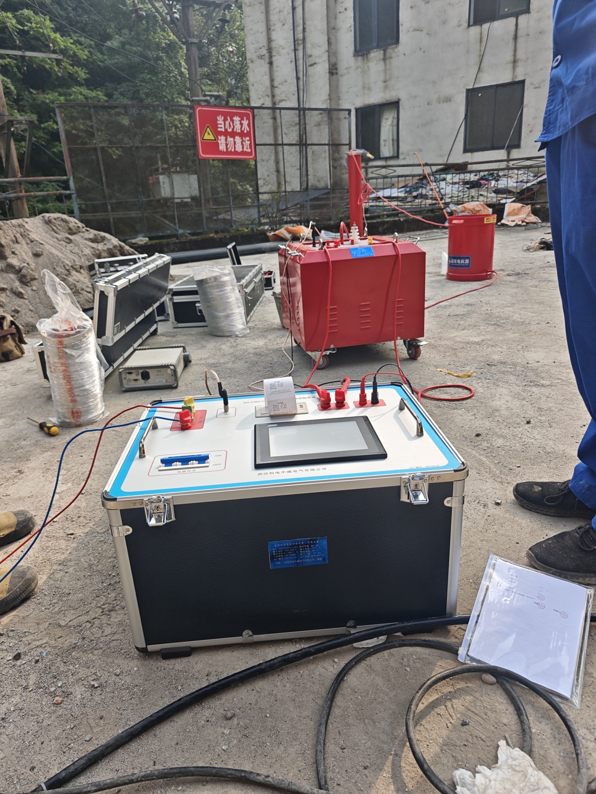
Upon arrival, our engineers surveyed the substation layout to identify the equipment under test, power access points, and grounding conditions. Workspace at the hydropower station was limited, requiring careful positioning to avoid interference with existing energized equipment and construction access routes.
Each reactor weighs 90kg, requiring 2-3 personnel for movement. Our engineers collaborated with the customer‘s team to complete reactor positioning and lifting. Reactor configurations for different tests were as follows:
-
10kV/35kV Cable Tests: Reactors connected in parallel to reduce total inductive reactance, matching the large capacitance of cables and increasing output current capacity. This project used 2 reactors in parallel for the 35kV cable test, and a single reactor for the 10kV cable test.
-
110kV GIS Test: All 6 reactors connected in series, providing a total output voltage of up to 270kV to meet the 265kV requirement.
IV. Test Procedure and Data Recording
1. 10kV Cable Withstand Voltage Test
The test object was the hydropower station service feeder cable, 300mm², approximately 1.5km in length. The variable frequency power supply was swept upward from 30Hz. At 42.3Hz, series resonance occurred and voltage rose rapidly to 22kV, maintained for 5 minutes.
Real-time parameters recorded during the test:
-
Output voltage: 22.1kV (RMS)
-
Output frequency: 42.3Hz
-
Excitation current: 38.7A
-
Quality factor (Q): 32.6
-
Waveform distortion: 0.4% (better than the ≤0.5% design specification)
2. 35kV Cable Withstand Voltage Test
The test object was the step-down substation incoming cable, 300mm², approximately 0.8km in length. After reconfiguring the reactors, the resonance point was found at 48.7Hz, and voltage was smoothly raised to 52kV, maintained for 60 minutes. Voltage fluctuation throughout was within ±1.2kV, fully meeting specification requirements.
3. 110kV GIS Withstand Voltage Test
The test object was the main transformer incoming bay GIS. All 6 reactors were connected in series. The variable frequency power supply was tuned to 135.2Hz, and voltage was raised to 265kV, maintained for 1 minute. The capacitive voltage divider (TRF-270/0.001, ratio 1000:1, accuracy 1.0%) monitored the high-side voltage in real time, ensuring accurate and reliable data.
V. Key Technical Features
1. Three Operating Modes – Flexible Switching
The system supports Manual Test / Auto-Tuning / Auto-Test modes. This project primarily used Auto-Tuning mode, where the system automatically sweeps frequencies, locks the resonance point, and ramps up voltage. This simplified operation and reduced the learning curve for the customer‘s field team.
2. Excellent Waveform Quality
Throughout all tests, the output voltage waveform remained sinusoidal with distortion ≤0.5%, exceeding standard requirements and ensuring test voltage purity.
3. Comprehensive Protection Functions
Overvoltage, overcurrent, overtemperature, and flashover protection were active throughout all tests. In the event of flashover, the resonant circuit automatically detuned, power output ceased immediately, and the screen displayed “Test Failed” with relevant information, effectively protecting both equipment and personnel.
VI. On-Site Training and Technical Guidance
A core component of this service was helping the customer‘s team gain independent operational capability. Training covered three modules:
Module 1: Equipment Assembly and Dismantling
-
Handling, positioning, and series-parallel configuration of 6 reactors
-
Selection of excitation transformer output voltages (2kV/4kV/12kV)
-
Installation and wiring of the capacitive voltage divider
-
Dismantling and packing procedures after use
Module 2: Parameter Setup and Operational Procedures
-
Functions and operation of each control on the variable frequency power supply panel
-
Input of equipment-under-test parameters and test settings (voltage, duration, frequency range)
-
Auto-tuning vs. manual tuning – application scenarios and switching
-
Voltage ramp control and resonance point fine-tuning techniques
Module 3: Safety Procedures and Troubleshooting
-
Pre-test grounding checks and safety confirmation workflow
-
Abnormal condition identification and emergency response during testing
-
Post-test discharge procedures
-
Routine maintenance and care of the system
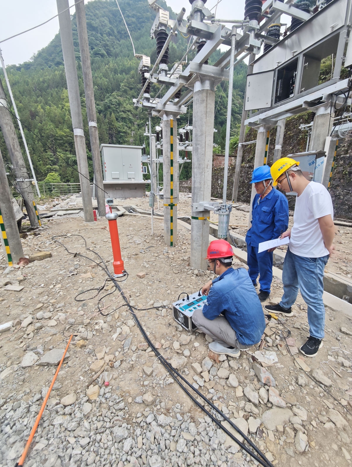
Four customer technicians participated in the full training program, taking turns performing equipment assembly, parameter configuration, and voltage-raising operations under our engineers‘ guidance. All were confirmed to have mastered basic operational procedures.
VII. Test Results
All withstand voltage tests for this hydropower station step-down substation renovation project passed on the first attempt:
| Equipment Under Test |
Test Voltage |
Duration |
Result |
| 10kV Cable (300mm², 1.5km) |
22kV |
5min |
✅ PASS |
| 35kV Cable (300mm², 0.8km) |
52kV |
60min |
✅ PASS |
| 110kV GIS Equipment |
265kV |
1min |
✅ PASS |
The customer‘s test lead confirmed satisfaction, particularly noting:
-
One system covering multiple equipment types: From 10kV cables to 110kV GIS – no need to change entire systems
-
Auto-tuning functionality: Fast resonance finding and precise locking, reducing on-site operational complexity
-
Comprehensive protection: Multiple protections active throughout, ensuring safe and reliable testing
-
Effective on-site training: Customer team is now capable of independent operation
VIII. Summary
This field application of the KDXZ-810kVA/270kV Variable Frequency Series Resonance Test System at a hydropower station step-down substation in Ya’an, Sichuan, fully demonstrated the system‘s adaptability across multiple scenarios. With flexible series-parallel reactor configurations from 6 reactors, a single system covered 10kV cables, 35kV cables, and 110kV GIS withstand voltage testing. Its compact size and flexible combination make it particularly suitable for confined workspaces such as hydropower stations.
Wuhan Kedi Zhongwei not only provides high-quality test equipment but also emphasizes full-process technical support – from equipment delivery to on-site training.
For inquiries about variable frequency series resonance test systems or other power test equipment, please contact Wuhan Kedi Zhongwei.